Conveyor Take-up Winches - NCIG Stage 2
| Project Ref: | 24425 |
| Client: | John Holland |
| Project: | NCIG Stage 2 |
| Scope: |
4 off – 8t Static Take-up Winches 1 off – 10t Static Take-up Winch |
Challenge:
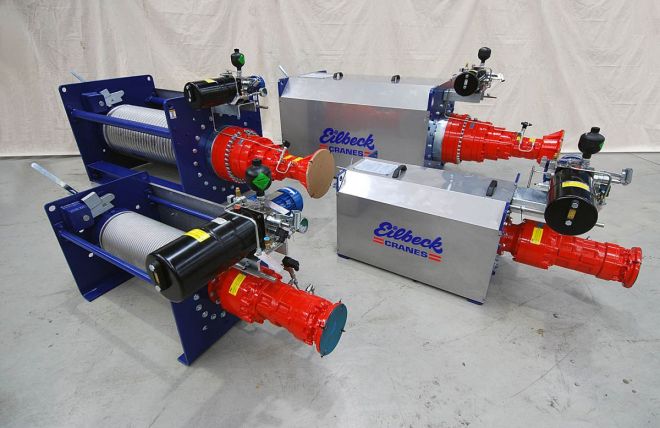
As we did on the first stage, Eilbeck Cranes again won the tender to supply static take-up winches for Newcastle Coal expansion stage two. The repeat order winches are designed with ratchet & pawl brake system which isolates the geared motor from the counterweight forces and allows the brake to engage & release over a number of high speed cycles and significantly increases the long term use of geared brake motor components. Also the winches are equipped with slack rope detector that shuts down the system when the rope is loose at any time. Simply, first class engineering with first class components!
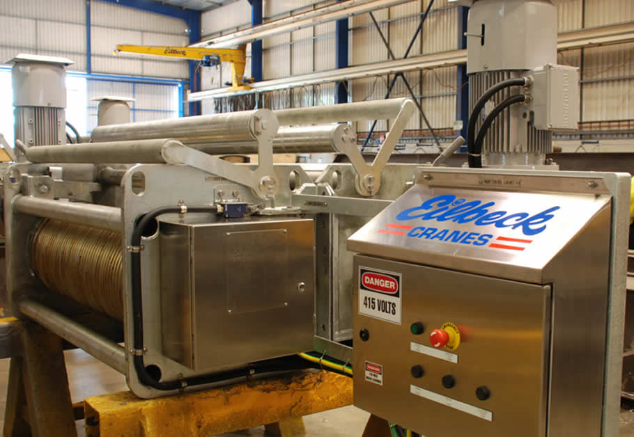
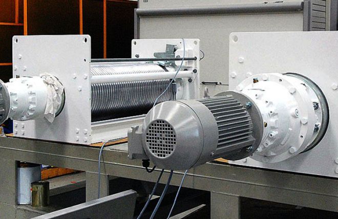
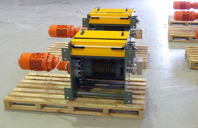
Physical Description of Equipment
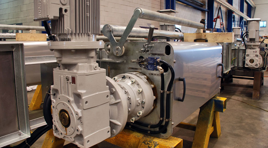
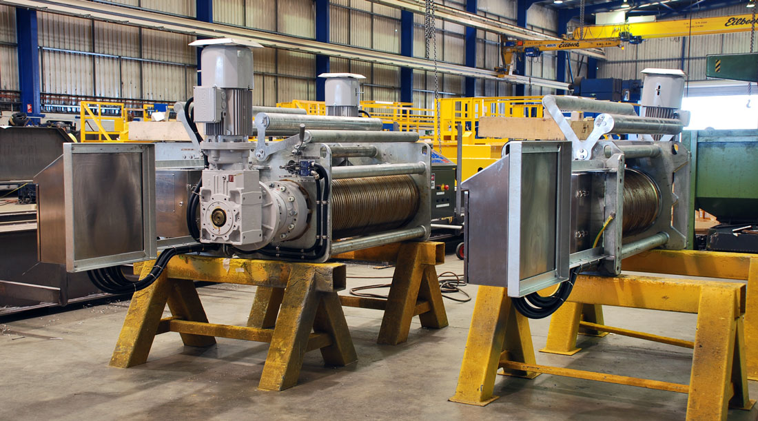
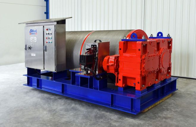
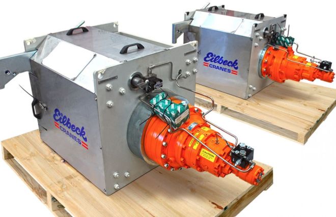
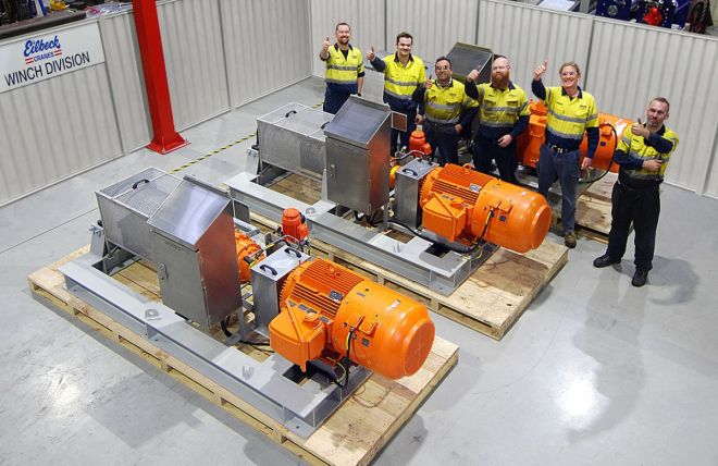
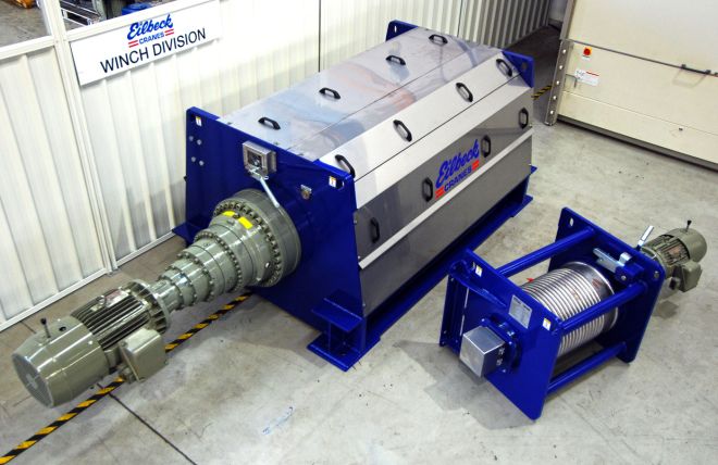
Each conveyor take-up winch is supplied as a fully assembled unit which consist of winch frame, rope drum, brake motor, bevel helical gear and planetary gear. The wire rope is also part of the winch.
Each unit mounted on a single base frame suitable for bolting either onto a concrete plinth and subsequent grouting or onto a steel structure.
The winch frame incorporates with sheaves (supplied by others) and an anchor point for the wire rope. Each conveyor take-up winch will act on the associated take-up pulley trolley via a sheaved cable system. The winch motor is a 3 Phase 415 V Squirrel cage induction motor, and includes an electro magnetic brake. The Local Control Station provides access to control the winch assembly. The following General Arrangement drawings (attached in section 1.4) describe the Take Up Winch Assemblies:
- HW02-C305.22-H-59838 – 8 T Take - up winch
- HW02-C305.22-H-59858 – 10 T Take – up winch
Theory of Operation
The Conveyor Take-Up Winch is required to maintain a tension in the associated conveyor belt. The Local Control Station provides access to control the winch assembly. The local control station enables the operator to drive the winch either in the forward or reverse direction. The winch will operate to increase or decrease the belt tension and this will be monitored by the local operator.
Functional Description of the Equipment
The take-up winches are installed on the conveyor gravity take-up tower. The winch is attached to the termination point of the take-up roller tensioning system. The winch positions the take-up weight in the tower such that it can travel freely and is also used to adjust the position of the take-up weight as the belt adopts its permanent stretch. The winch is also used to lower the take-up weight removing tension from the conveyor belt for maintenance purposes. The winch is stationary unless operated manually.
The winch is designed to be operated between preset limits. Control of operation is carried out via push buttons located on the front of the winch control panel.
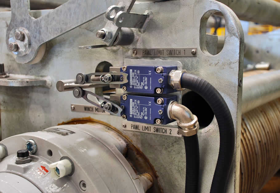
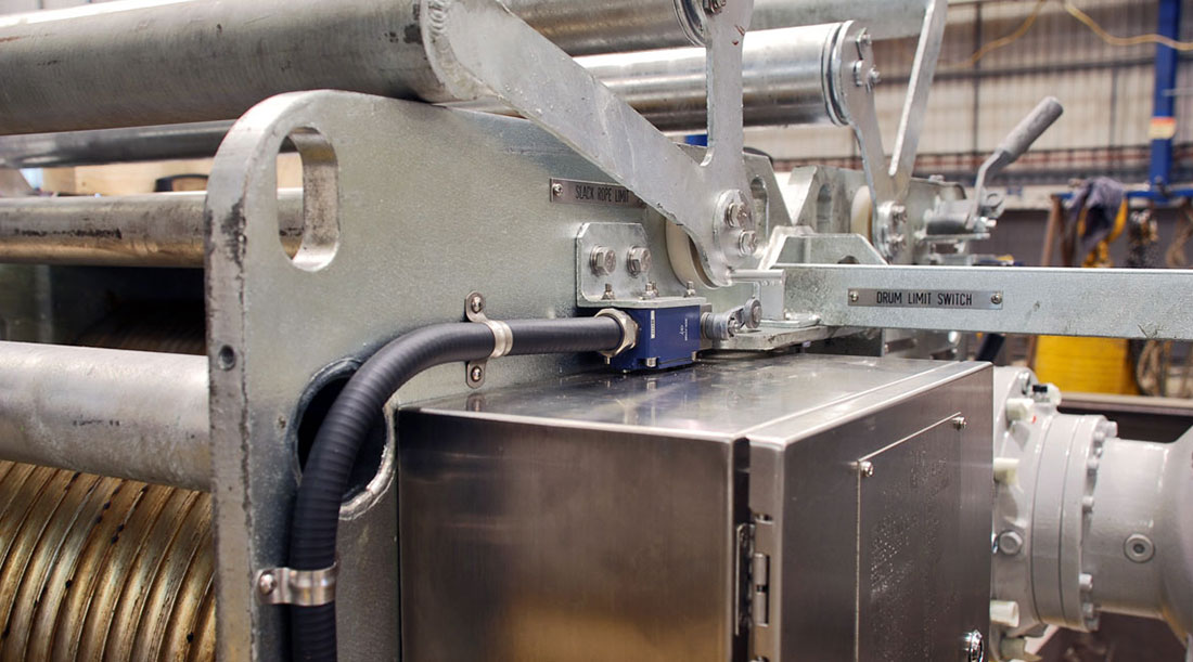
To turn the winch ON the EMERGENCY STOP must be released, the rope must be under tension and the drum must not have travelled past the final limits. If these conditions are met the main contactor will be energised when the START button is depressed. If one of the srart up conditions change, the winch will turn OFF.
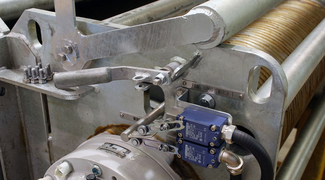
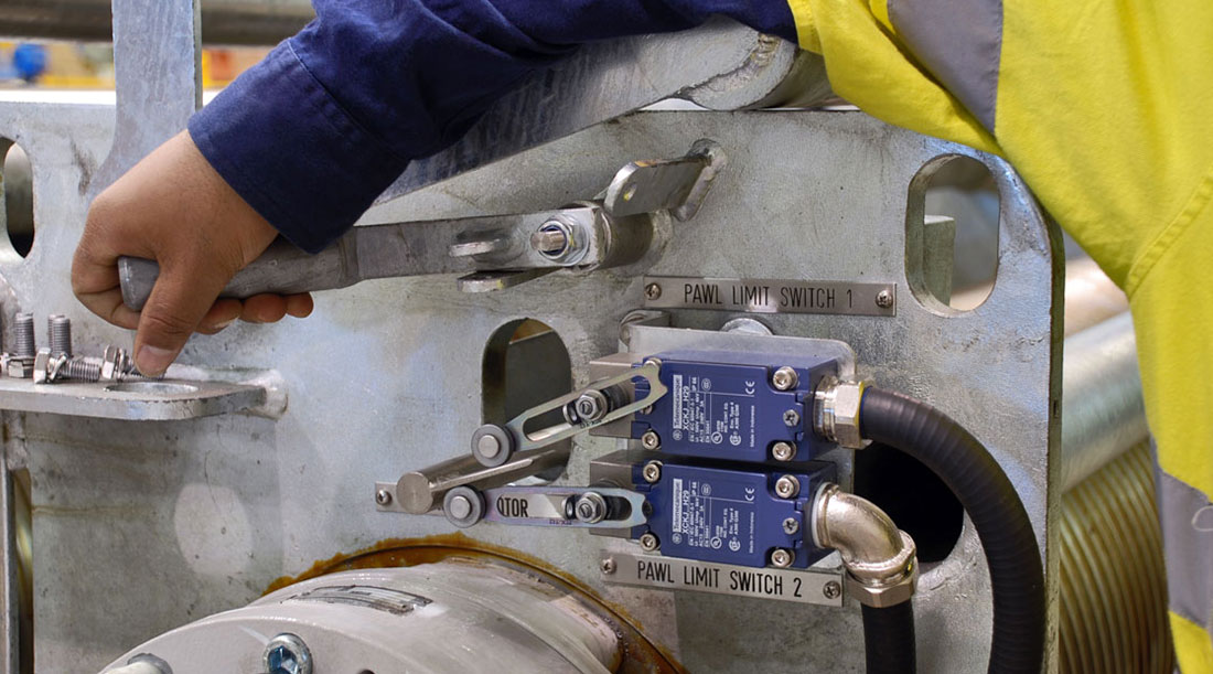
Once the winch is turned ON the FORWARD and REVERSE buttons can be used to control the winch. The winch will not operate until the pawl brake is released. FORWARD and REVERSE motion are interlocked with the pawl brake limit switches.
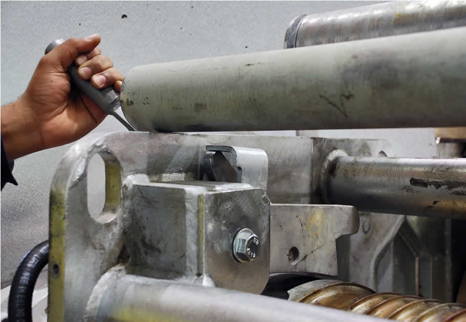
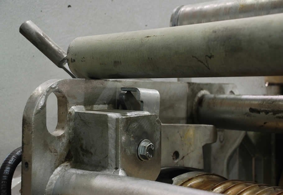
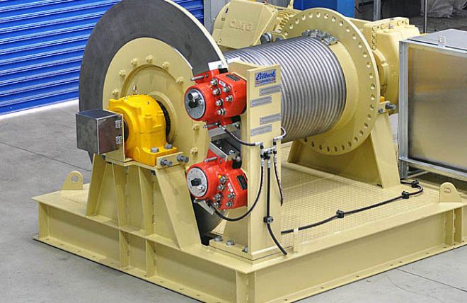
Brakes
The winches have been designed to incorporate 2 separate braking systems. An automatically operating electromagnetic brake is fitted to the electric motor for normal winching operation.
A secondary brake comprising of a ratchet and pawl style brake is fitted to the winch frame to allow for physical load isolation of the drum. The pawl handle has been designed with a lockable tab to allow for isolation of gravitational potential energy. While in the isolated position the pawl limits prevent electrical operation of the winching motions. It is recommended that for static load isolation both the winch power isolator and pawl brake be isolated.